The Hexkeypad can be plugged into either the JP1 or JP2 40-pin expansion headers. Once plugged in it is automatically connected to the lower 8 bits of that header and ignores the rest. The lower 8 bits are connected directly the 4 row pins and 4 column pins (so 8 pins in total) as shown further below.
| Device | Hexkeypad | |||||||||||||||
| Input/Output | either | |||||||||||||||
| Address Base | JP1=0xFF200060, JP2=0xFF200070 | |||||||||||||||
| Address Map |
| |||||||||||||||
| Initialization | Set direction register bits so that either rows are inputs and columns are output, or vice versa. | |||||||||||||||
| Interrupts |
| |||||||||||||||
| Hardware Setup | Connect the 40-pin ribbon from the hexkeypad to either port JP1/2 on the DE1-SoC | |||||||||||||||
| Reference | Hexkeypad Tutorial |
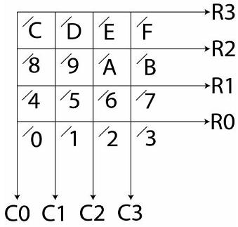
The hexkeypad is arranged as a 4x4 matrix of wires, and note that they are ONLY wires, no circuitry or logic other than pull-up exist. When you press a button the two wires touch, so to figure out when a key is pressed you need to configure, for example, the rows as outputs and the columns as inputs. You can then drive the rows low and see if any column pin turns low (since the hexkeypad is active-low as explained below). For example, if you press number 5 on the hexkeypad, that connects pin R1 to C1 so if you set R1 as a low output you would see it low on C1 if it was an input, and if you set C1 as a low output you would see low on R1 if it was an input. See the referenced Documentation above.
Active-low - The pins of the hexkeypad are set to be "pulled-up" to logical 1 (or high) by default, so if nothing is being pressed you should read 1's. You should hence drive the output pins low and observe which input pin is low.
Acknowledging interrupts - Interrupts are triggered when any bit in the Edge Capture Register is high. For the hexkeypad this usually means an interrupt gets generated when you first press a button. Make sure you clear the edge capture register before you enable interrupts and before you exit your interrupt handler.
The image below shows how the pins connect to the 4 row and 4 column pins of the hexkeypad.
| Port Bit | Hexpad Pin |
| 0 | R0 |
| 1 | R1 |
| 2 | R2 |
| 3 | R3 |
| 4 | C0 |
| 5 | C1 |
| 6 | C2 |
| 7 | C3 |
.equ ADDR_JP1PORT, 0xFF200060

  movia r2,ADDR_JP1PORT
  movia r3,0xf0
  stwio r3,4(r2)  # Set directions - rows to input, columns to output

  stwio r0,(r2)   # Drive all output pins low

  ldwio r3,0(r2)  # Read port data
  andi  r3,r3,0xf # Mask out all but last 4 bits
.equ ADDR_LEDR, 0xFF200000
.equ ADDR_JP2PORT, 0xFF200070
.equ ADDR_JP2PORT_DIR, 0xFF200074

.global _start
_start:

  movia r2,ADDR_LEDR
  mov   r5,zero   # Start display at 00000000
  stwio r5,0(r2)  # Write to LED displays

  movia r2,ADDR_JP2PORT_DIR
  movia r3,0x000000f0
  stwio r3,0(r2)  # Set rows to input, columns to output

  movia r2,ADDR_JP2PORT
  stwio r0,(r2)   # Drive all output pins low

LOOP:
  movia r2,ADDR_JP2PORT
  ldwio r3,0(r2)  # Read port data
  movi  r4,0xf
  and   r3,r3,r4  # Mask out all but last 4 bits

  beq   r4,r3,LOOP

  movia r2,ADDR_LEDR
  xori  r3,r3,0x0f # Invert bits to drive LEDs
  stwio r3,0(r2)  # Write to LED displays

                  # Debounce loop
  movia r9,10000000
DELAY:
  subi r9,r9,1
  bne r9,r0, DELAY

  br _start
/*****
 * Gets a NON-DEBOUNCED key from the keypad. Note that this also shows the
 * use of procedures and functions in C.
 *
 * This program detects a key pressed on the hexkeypad and displays it on the
 * red LEDs by lighting the corresponding LED
 *****/

#define ADDR_JP1PORT ((volatile long *) 0xFF200060)
#define HEXPAD_DIR ((volatile long *) 0xFF200064)
#define ADDR_LEDR ((volatile long *) 0xFF200000)
unsigned char colstims[]={0xe0,0xd0,0xb0,0x70}; //to run the hexpad


// start the hex keypad
// note that since this uses the GPIO interface you must set the
// directions of the individual bits. See the section on GPIO for
// more information.
void HexkeypadInit()
{
   *HEXPAD_DIR = 0xf0; // set directions . rows in, cols out
   *ADDR_JP1PORT = 0x0f; //set all rows to high
}

// return key found pressed, -1 if no key pressed
// note: if multiple keys pressed, returns the first key
// does not debounce key!
char HexkeypadIn()
{
  // Wait until a key is pressed
  int rowRead = (*ADDR_JP1PORT) & 0x0f;
  while (rowRead == 0x0f) {
    rowRead = (*ADDR_JP1PORT) & 0x0f;
  }

  // Key has been pressed!  Debounce!
  int d = 0;
  while (d < 100) {
    d++;
  }

  // Switch to read columns

  *HEXPAD_DIR = 0x0f; // rows out, cols in
  *ADDR_JP1PORT = 0xf0;  // set all cols to high

  // Process rows
  //rowRead = (*ADDR_JP1PORT) & 0x0f;
  rowRead = rowRead ^ 0x0f; // invert the number
  // Set it to first confirmed row
  if (rowRead & 0x01) {
    rowRead = 0;
  } else if (rowRead & 0x02) {
    rowRead = 1;
  } else if (rowRead & 0x04) {
    rowRead = 2;
  } else if (rowRead & 0x08) {
    rowRead = 3;
  } else {
    rowRead = -1;
  }


  // Read column
  int colRead = (*ADDR_JP1PORT) & 0xf0;
  // Process column
  colRead = colRead ^ 0xf0; // invert the number
  // Set it to first confirmed column
  if (colRead & 0x10) {
    colRead = 0;
  } else if (colRead & 0x20) {
    colRead = 1;
  } else if (colRead & 0x40) {
    colRead = 2;
  } else if (colRead & 0x80) {
    colRead = 3;
  } else {
    colRead = -1;
  }

  // Reset rows and columns
  *HEXPAD_DIR = 0xf0; // rows in, cols out
  *ADDR_JP1PORT = 0x0f;  // set all cols to high

  // Determine from rows and columns which key was pressed
  char numRead = -1;

  if ((rowRead != -1) && (colRead != -1)) {
    numRead = (char) (4*rowRead) + colRead;
  }
  return(numRead);

}


int main()
{
   char inputkey;

   HexkeypadInit(); //this is a procedure to start the keypad

   while (1)
   {
      inputkey = HexkeypadIn(); //function, returns key pressed
      if (inputkey != -1) {
	    int i;
		int val = 1;
	    for (i = 0; i < inputkey; i++)
		{
		  val = val << 1;
		}
        *ADDR_LEDR = val;
      }
   }
}