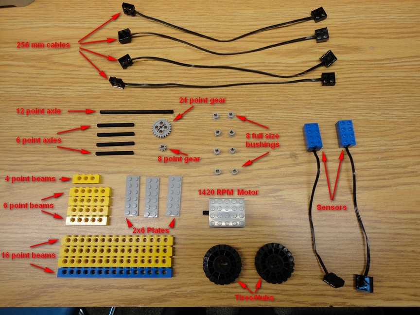
- 4x - 256mm cable
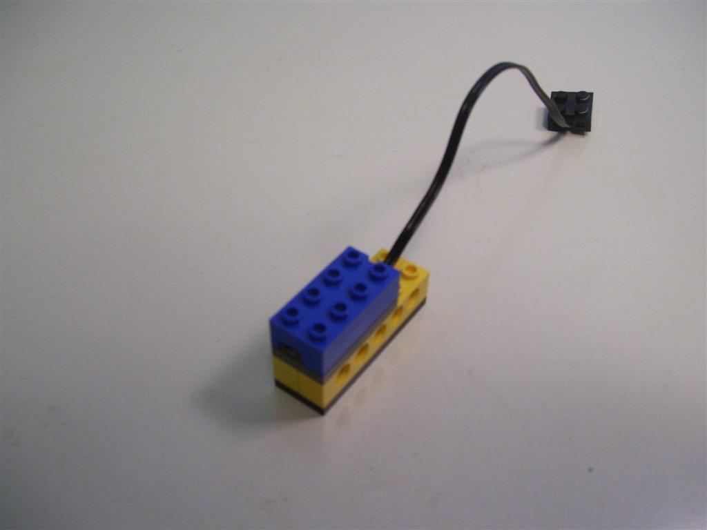
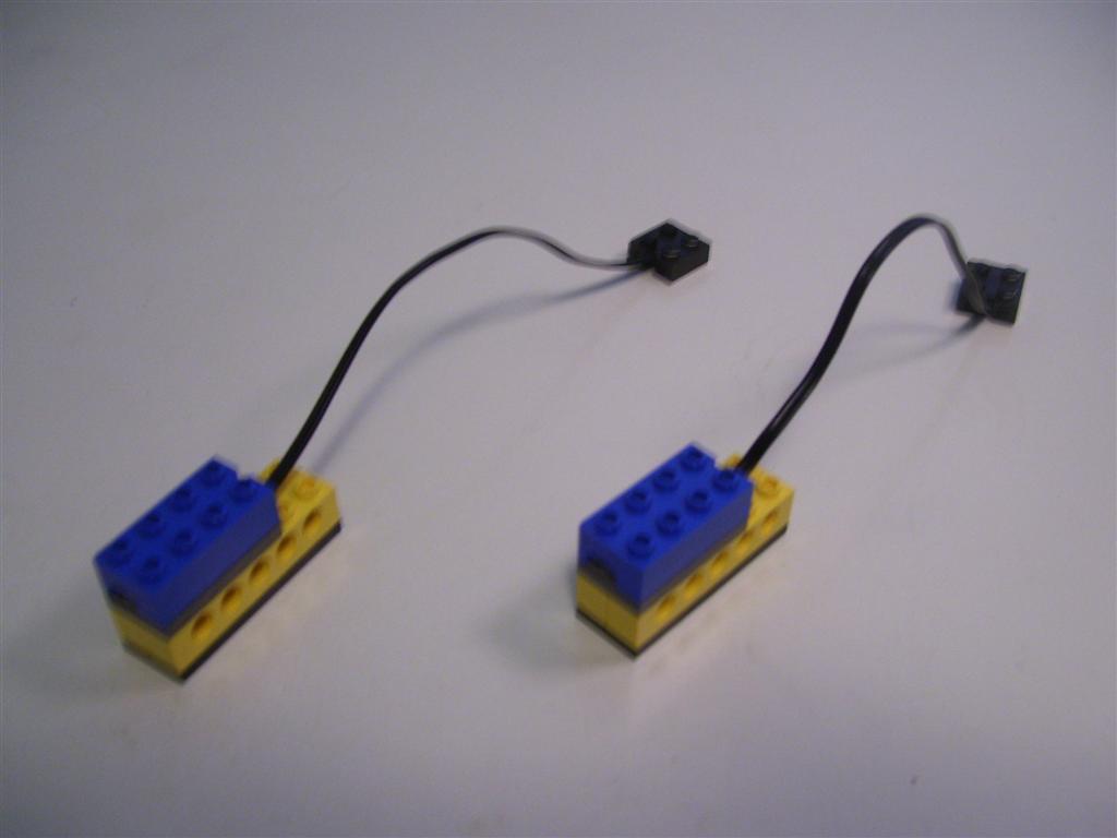
- 2x - sensors
- 1x - basic motor (1420 RPM)
- 1x - 4 point beam
- 4x - 6 point beams
- 4x - 16 point beams
- 4x - 6 point axles
- 1x - 12 point axle
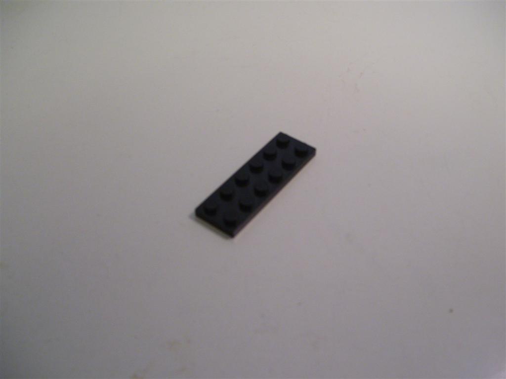
- 3x - 2x6 plates
- 8x - full size bushings
- 1x - 24 point gear
- 1x - 8 point gear
- 2x - tires/hubs
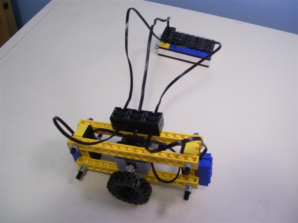
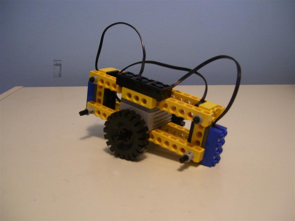
The device consists of a frame and a Lego motor balanced on a single axle with two wheels. At each end of the frame is a Lego sensor that faces towards the ground. Each sensor measures its distance from the ground based on the reflection of a built in LED. The closer the sensor is to the ground, the more light it senses, the higher the value it reports. By examining the values of both sensors, the device can determine if it is tilting in one direction or another and rolls in the direction that will correct that tilt.
To build the balancing device you will need the following parts which can be found in your Lego kit:
|
|
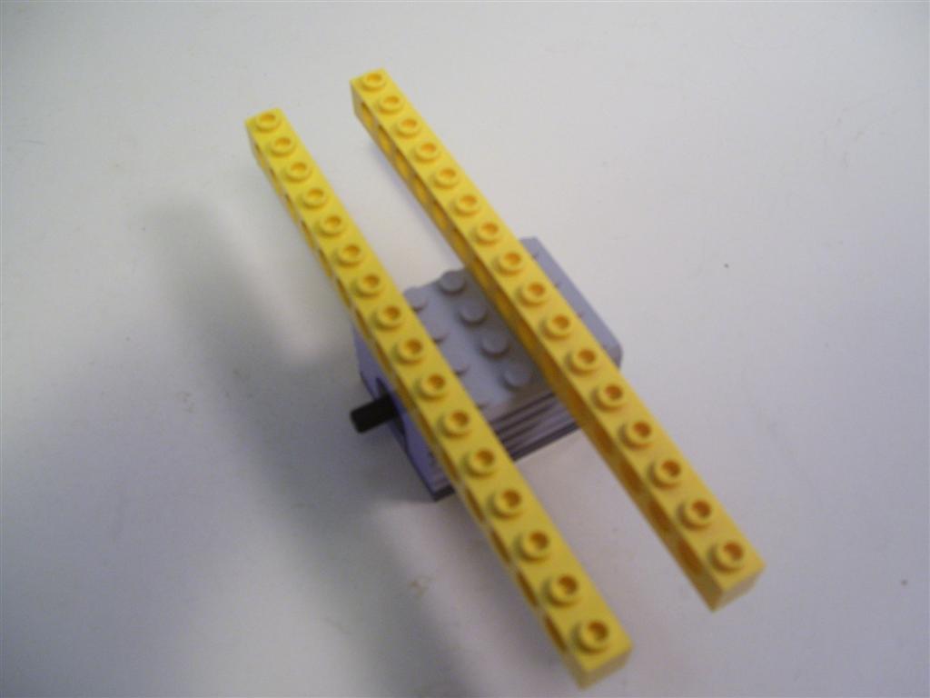
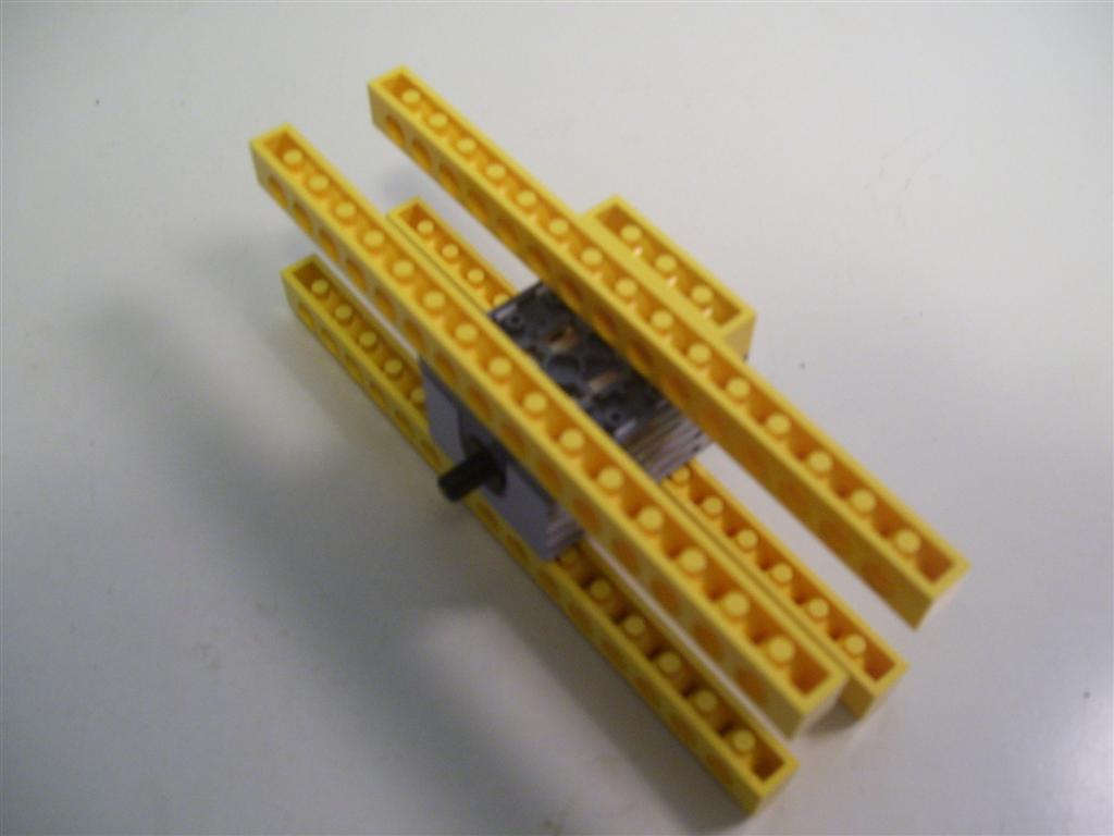
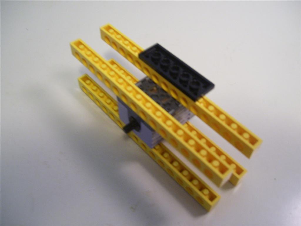
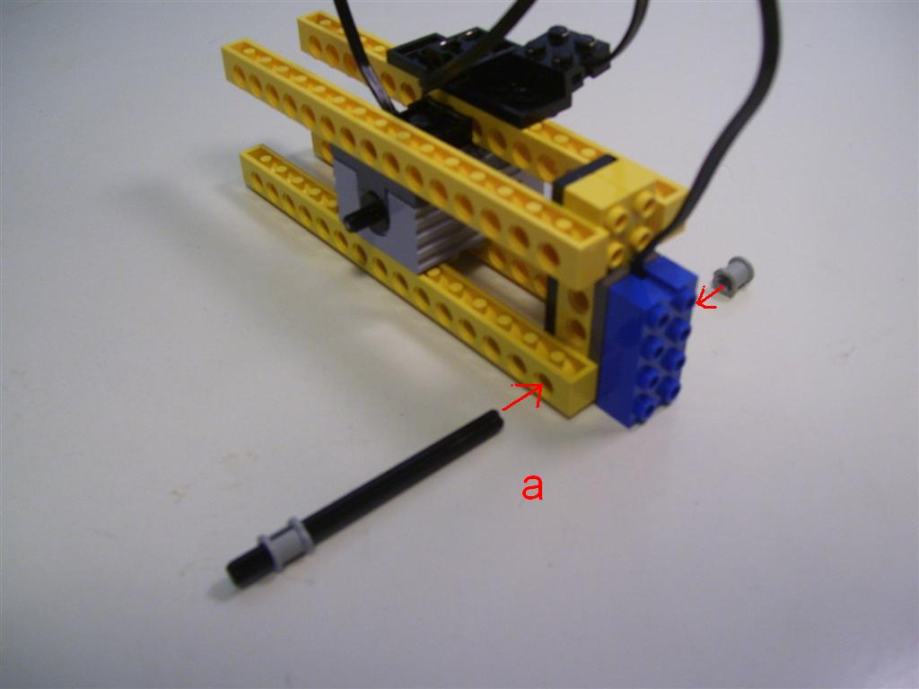
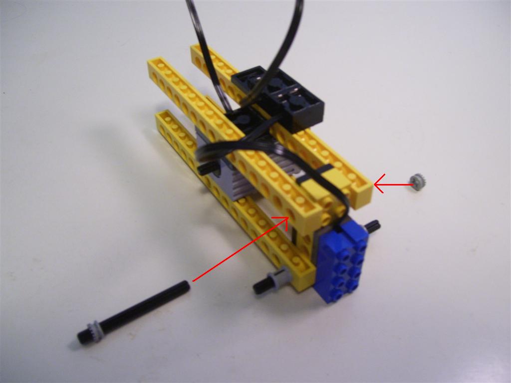
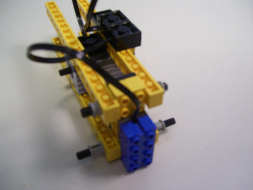
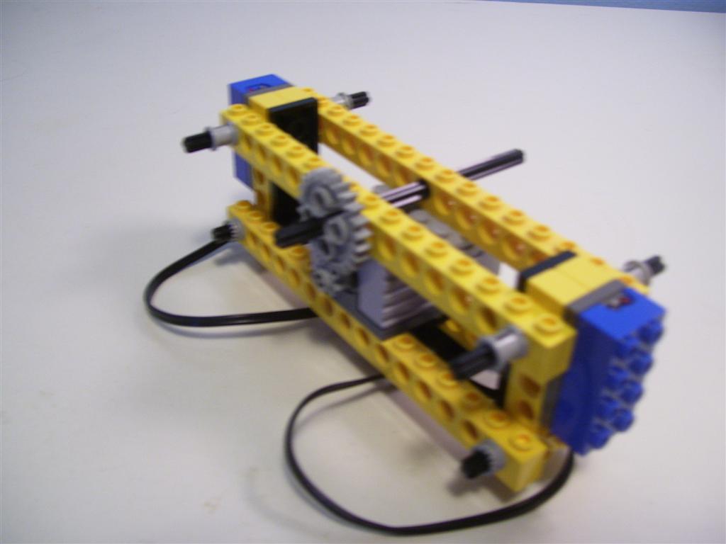
Follow these instructions to build your balancing device. Keep in mind that the device should be physically symmetric about the axle of the motor so that it can balance.
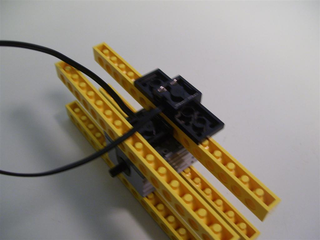

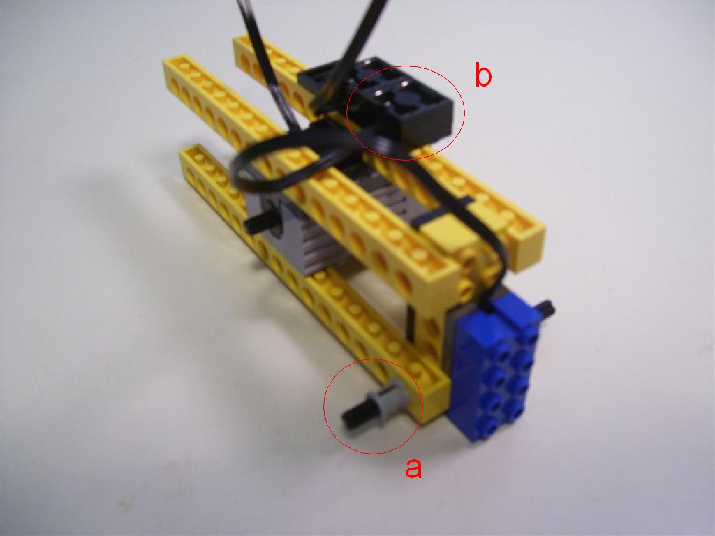
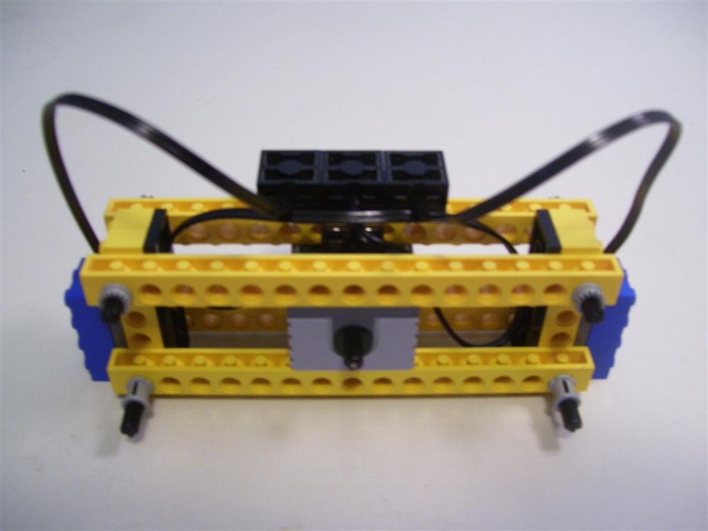
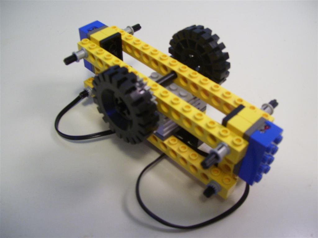
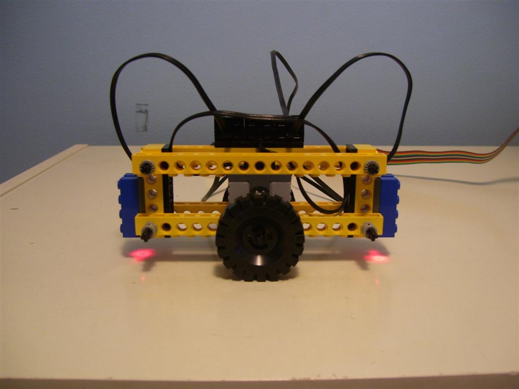
Flip the device over. Make sure your device looks like the one pictured below.
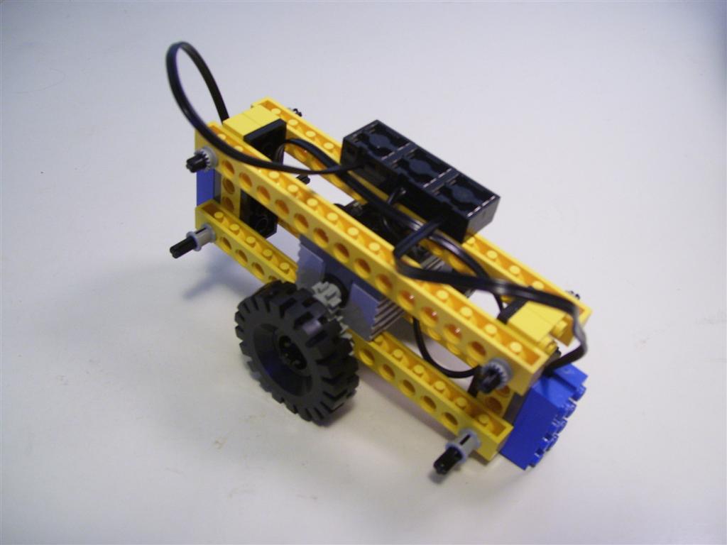

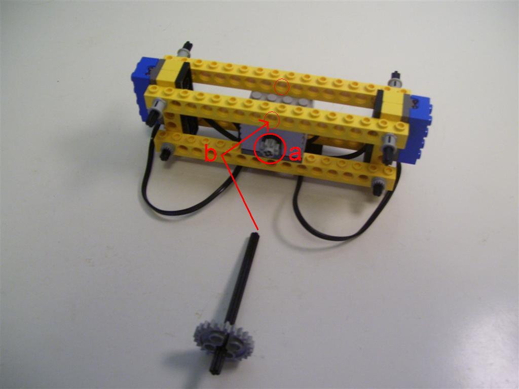
Now, use the other three 256mm cables to connect the motor and sensors to the breakout box. NOTE: you will want to keep the cables parallel to the axle, and give the cables a bit of slack. This is to make sure the wires don't affect the balance of the device.